Omer – Move 30 L
Description
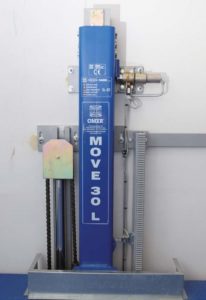
Overall view
of the unit (to ensure easy understanding, the photos were taken during maintenance because the doors cannot be opened unless the platform is at floor level).
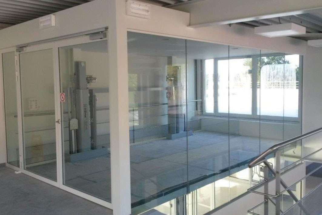
At the maximum travel
height, the piston assembly, guide-shoulder and lock mechanisms protrude by 1,618 mm.
The shoulder-guide can be hidden for protrusion-free platforms where the top part does not protrude at all. In this case, the depth of the pit must be increased from 215 mm to 1,715 mm.
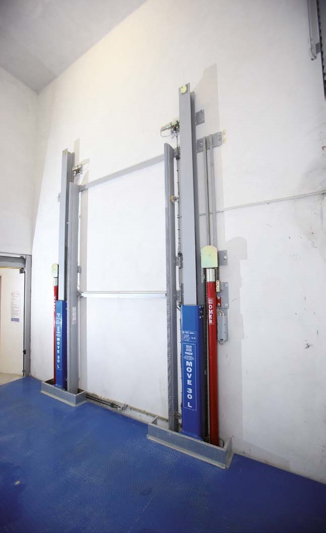
Front view of the columns once the machine has been installed. Besides the columns, the photo shows the two pistons, shoulder-guides, torsion bar positioning rack and piston assembly for mechanical locking to the floor, including spacers between columns.
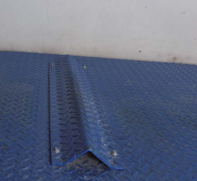
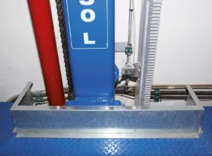
Detail of how the front wheel stop to guarantee
that the vehicle is properly positioned and to prevent it from shifting while the platform is being moved. Another such stop is found at the back.
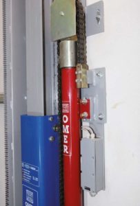
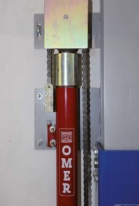
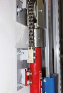
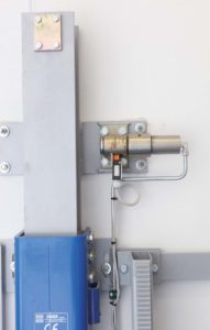
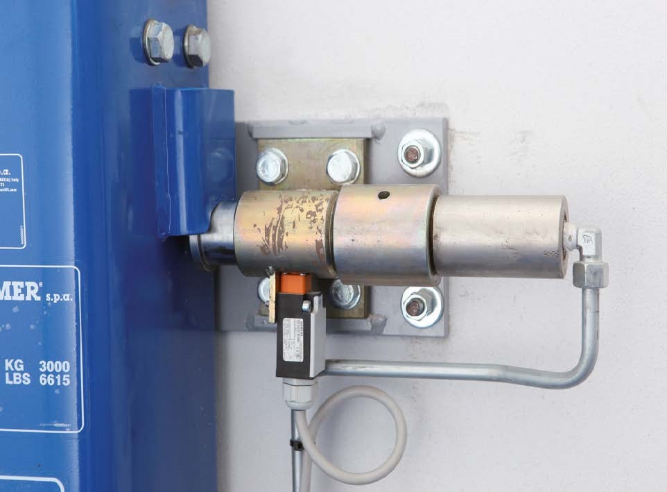
Detail of how the column
is secured to the wall using plates prewelded to the column and chemical anchors. The photo also provides details of the lift chain and pulley connection.
A protection is secured on the outside of the pulley to prevent the chain from leaving its seat.
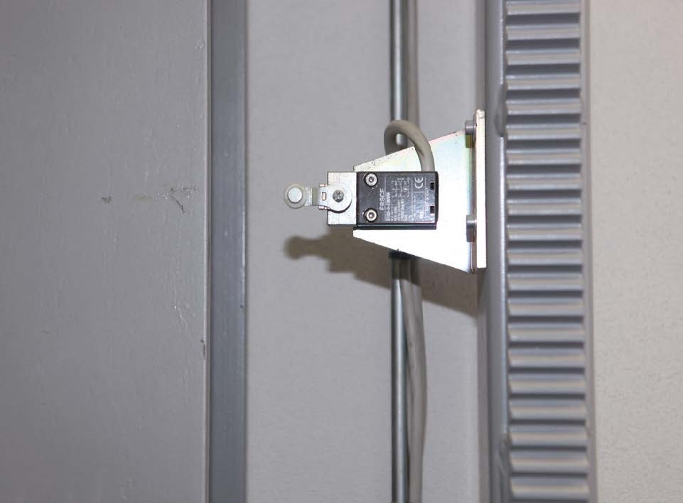
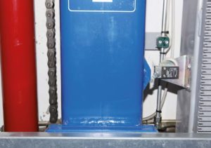
The photo upper shows an example of the limit switch positioned on the unit.
At the bottom, the photo shows the deceleration and travel regulation limit switch in action, highlighting the length of the operating cam (longer than the stop cam).
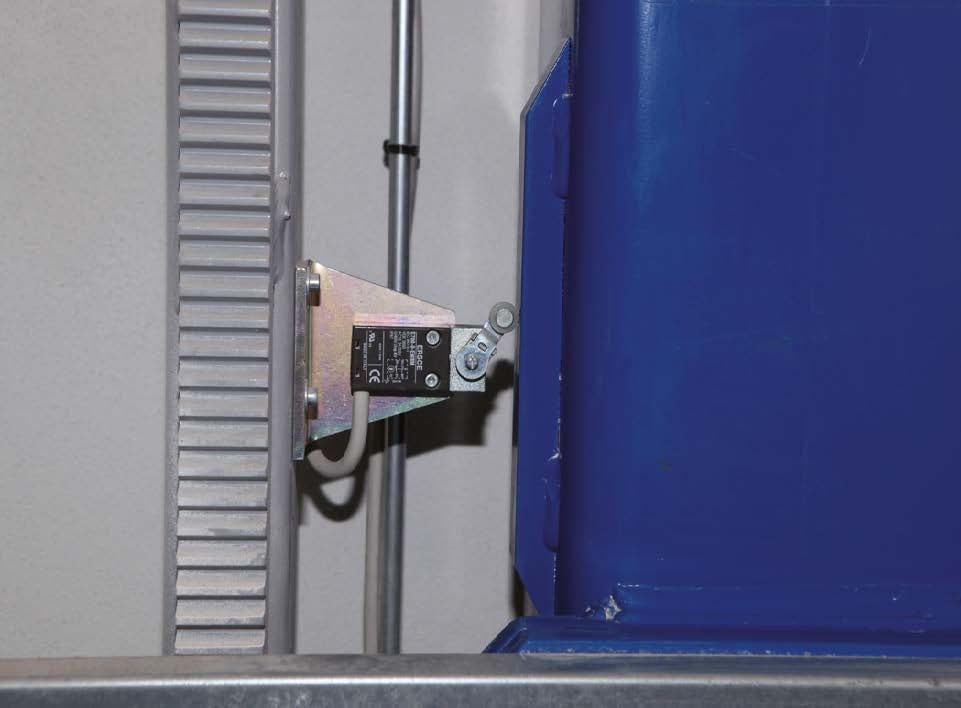
Instead, this angle shows the operation of the stop limit switch, located on the column opposite the deceleration limit switch, and highlights the shorter operating cam.
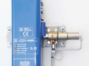
The mechanical locking
This series of photos shows the mechanical assembly that hydraulically locks the platform to the floor.
Then the shoulder drops
down again and thanks to the connection groin it rests on the piston itself, protruding from its housing and ensuring overall stability. At this point the hydraulic lift system of the two pistons under the platform revert to the resting position, preventing the continuous stress the hydraulic circuit would be subject to if they were to remain constantly pressurized.
Note that this platform does not present any movement as the vehicle drives on, a condition which would be seen if the platform were supported only by the pressure of the pistons. Indeed, this condition is easier on the user’s peace of mind.
The piston that mechanically
locks the unit to the floor is further controlled by an “all out, all in” limit switch that analyzes the correct position. In case of piston malfunction – when it is not possible to set the platform in safety mode with pulsed operation from the electrical control panel – the limit switch sends the platform to the next floor so that it can then be secured. The shoulder of the platform passes beyond the point where the piston is mechanically blocked to the floor, thus allowing it to protrude.
The head pinion
on the torsion bar has a notched ring (one on each end) that is engaged and runs along the rack (one per column). The same torsion bar has position-adjustable supports so that it is perfectly connected to the racks.

Manufacturer’s website : Omerpark
Product website : Omerpark-Move-30L